Dicty-Electroporator.github.io
Low cost device to genetically transform Dictyostelium discoideum
Dictyostelium discoideum Electroporator
Easily constructed by investigators with no electronics knowledge, we present an inexpensive and open-source electroporation apparatus for Dictyostelium discoideum with all functional modules and peripherals from Cauchy et al., 2022, "A Low-cost Electroporator for Genetically Modifying Social Amoeba Dictyostelium discoideum" submitted to Journal of Open Hardware.
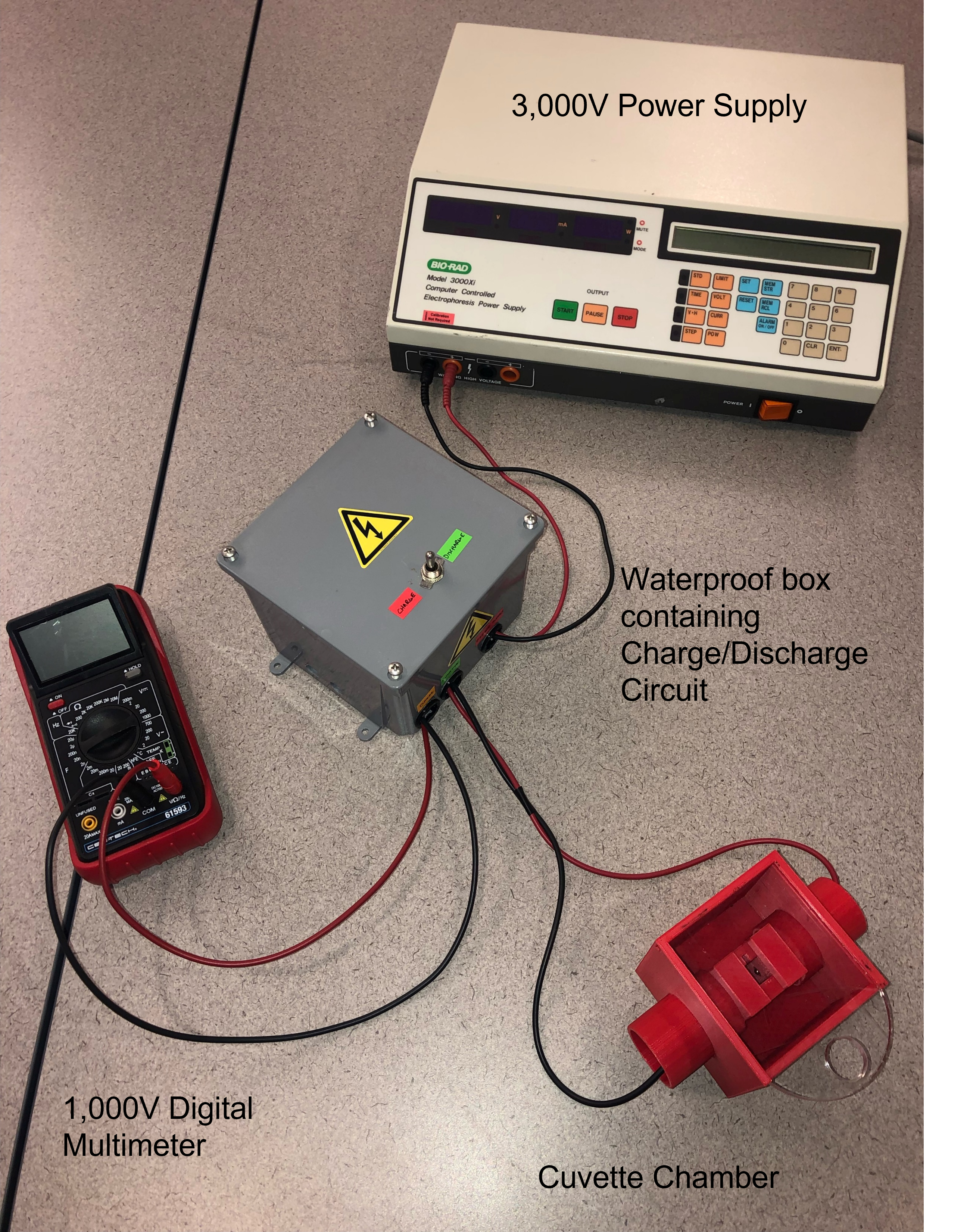
Description: Electroporation to introduce DNA into cells is a common technique in genetic engineering. Dictyostelium discoideum is a well-established eukaryotic model organism that is frequently genetically modified (transformed). We present here an electroporator capable of high efficiency transformation. Our electroporator consists of a high voltage power supply, pulse generator circuit and cell sample cuvette chamber. The power supply is programmed to deliver desired voltage, which when activated by a double-pole, double-throw switch (DPDT) charges a capacitor. Further switching allows the charged capacitor to deliver a precise, consistent exponential decay wave of the proper duration to the cuvette containing a D. discoideum cell and DNA mixture. The high-voltage circuit is housed in an electrically insulated enclosure - we chose a plastic electrical junction box with appropriate holes for switch mounting and cables to pass. A 3D printable cuvette holder was designed and is available in .stl, .dwg and .iges formats. An inexpensive 1,000-volt digital multimeter was integrated into the design to aid in development and testing. To provide hands-free monitoring of the real-time capacitor voltage, we connected multimeter test leads to the capacitor poles. In addition to the standard build, we present here an alternative design for the pulse generator, which we will refer to as "modular". The standard pulse generator was designed to be durable for repeated use in multiple D. discoideum electroporation experiments. This design includes a soldered padboard with high power rated components. The modular pulse generator is designed for ease of build, is easily modified by swapping components for alternative waveforms, and is intended for a small number of electroporations and not routine or repeated use.
License: CERN Open Hardware License
D. discoideum Electroporation System
Standard Pulse Generator
The pulse generator circuit features a soldered breadboard with high power components. Assembly is straightforward and can be constructed by a beginner with access to soldering equipment. The cuvette chamber features a built-in enclosure with limited access to the power connectors as well as a removable lid. The lid can be 3D printed or laser cut from a sheet of acrylic or other material. 3D design and print files are available on this page. We chose a biodegradable and fire-resistant 3D print media, Polylactic acid (PLA). Other cost effective, readily available, and more durable print media are available. The system was tested and performs as efficiently as a commercial electroporator.
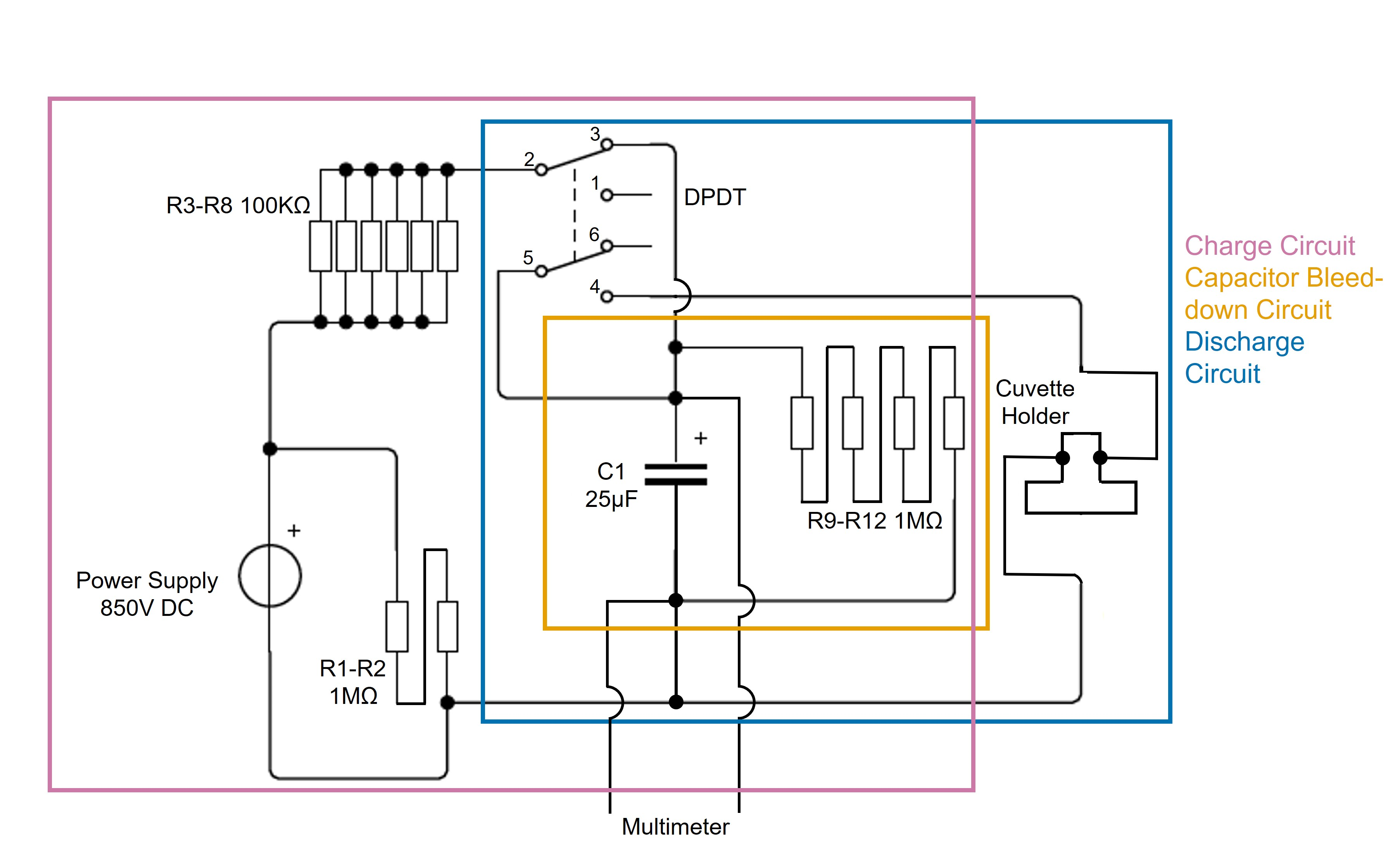
2W (Watt)-1MΩ (Ohm) resistors were used for resistors R1-R2 and R9-R12. 8W-100kΩ resistors were used for resistors R3-R8.
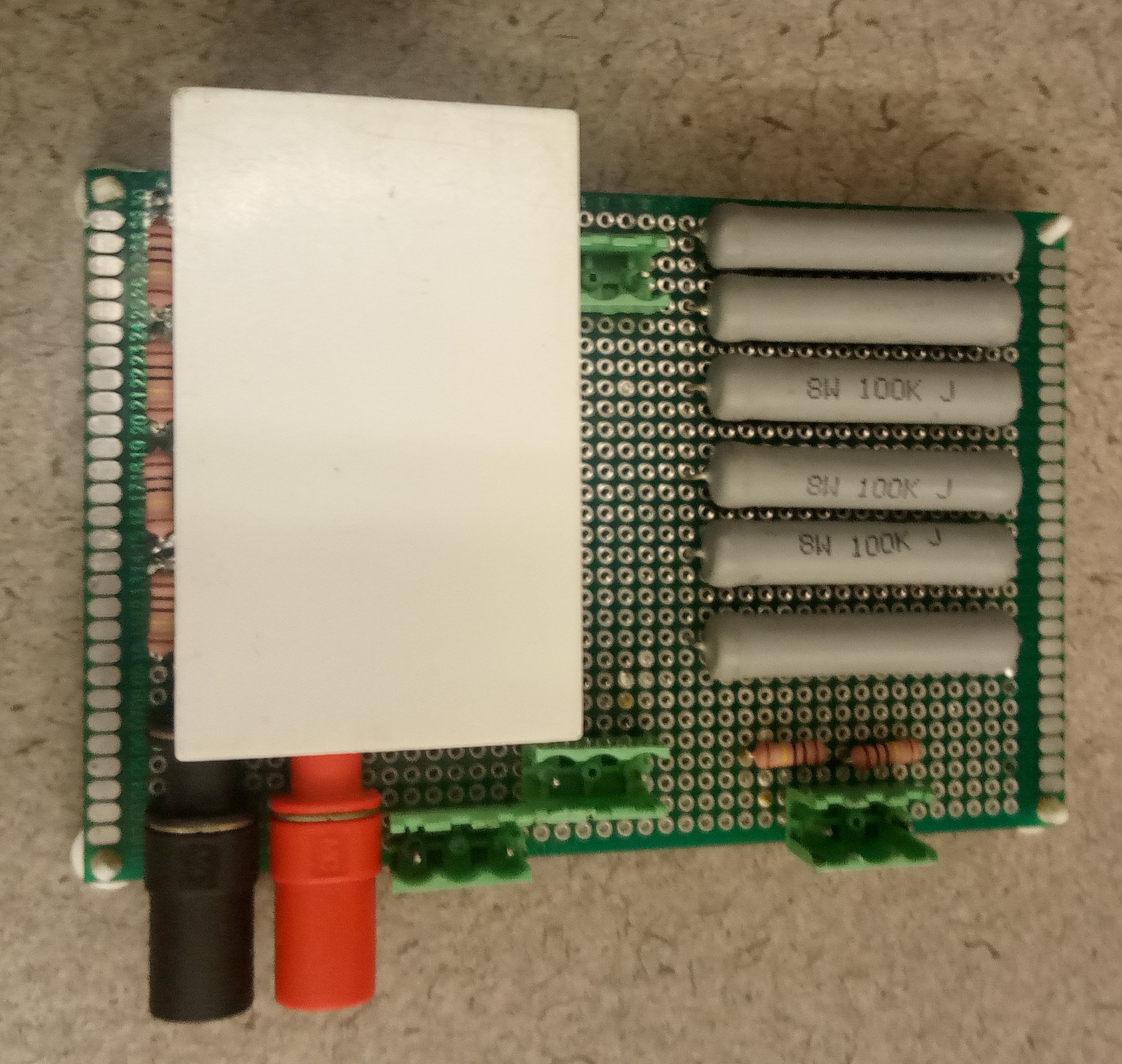
Components were fixed to the breadboard using the long leads of resistors as traces on the underside of the 8cm x 12cm padboard.
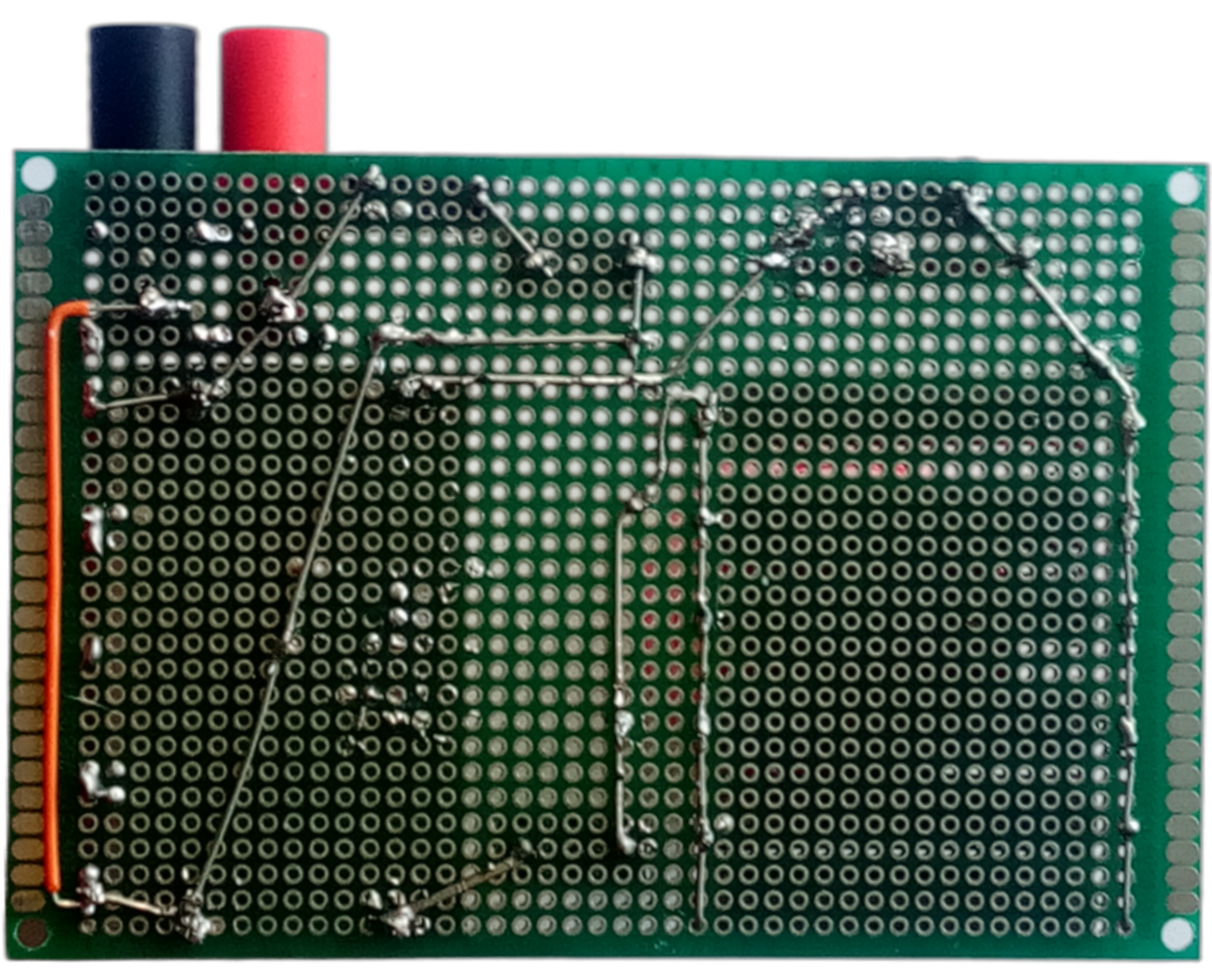
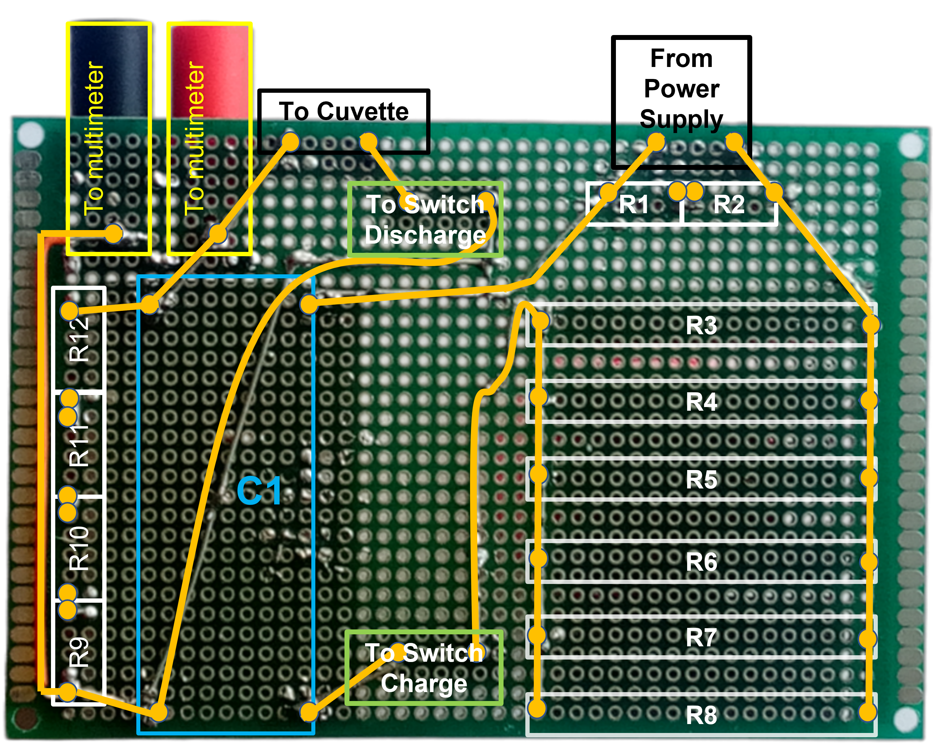
Trimmed resistor terminals and solder were used to create traces. This layout accommodates the lack of premade traces found on solderless breadboards. In addition, banana jack connectors were soldered to the component side and traced to the opposing capacitor poles at each end of the bleed-down resistor array. This allows connection to a multimeter and real-time monitoring of the capacitor voltage during electroporation and provides assurance the capacitor is safe.
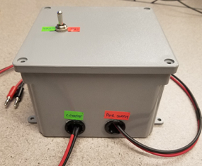
Enclosure
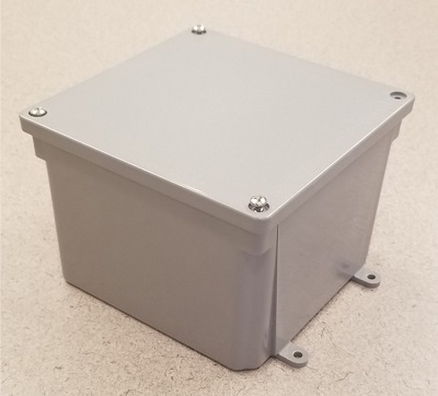
We chose a commercially available plastic junction box to enclose our pulse generator circuit. A 13mm hole was drilled into the enclosure cover for the DPDT and 22mm holes were marked and drilled in the enclosure which provided a nice fit for the plastic NM connectors and pass-through cables.
Assembly instruction
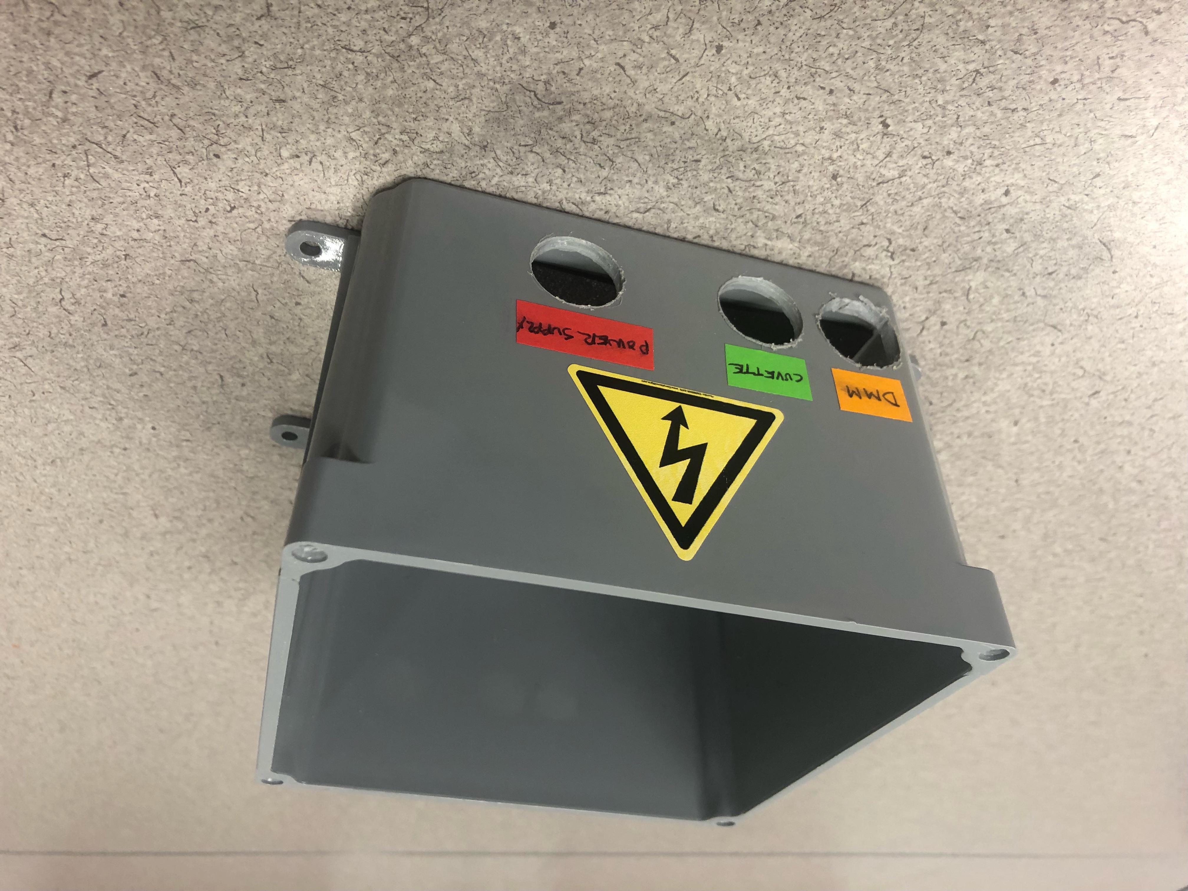
Drill three 22mm holes in any side of the enclosure. Label the holes as shown. DMM above refers to digital multimeter.
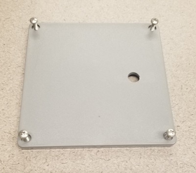
Drill 13mm hole in enclosure lid for switch mounting. Place the hole where hand-switching will be most comfortable.
Switch wiring
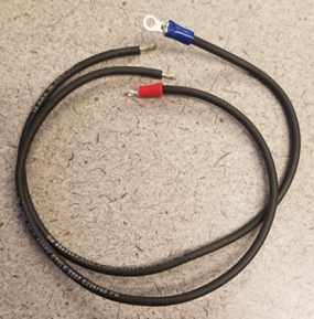
Cut 4 pieces of 18 AWG wire (for the switch) to 30cm lengths and strip approx. 5mm of bare wire from each end. Crimp one end of each wire to a ring terminal.
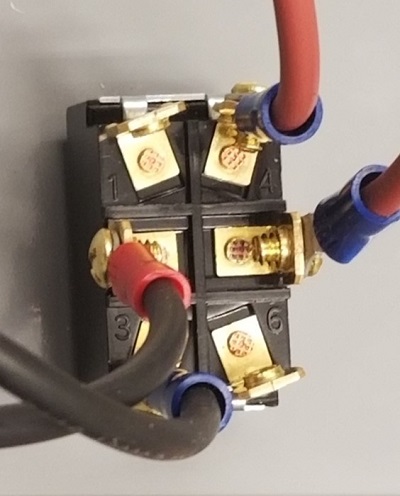
Attach ring terminals (with wire from step 1) to terminals 2, 3, 4, and 5 of the DPDT switch. Install switch into hole drilled into lid of case.
Using the 4 pieces of 18 AWG wire with ring terminals from step 1, connect switch terminals 2 and 3 to the outboard ports of one terminal block and 4 and 5 to the outboard ports of another terminal block. Insert paired wires into outside wire cages of terminal blocks, then tighten terminal block screws.
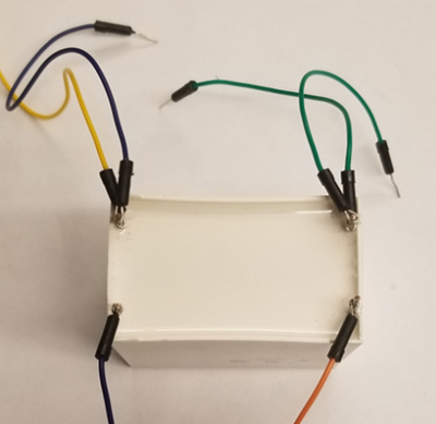
Cuvette Chamber
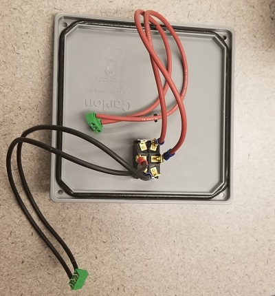
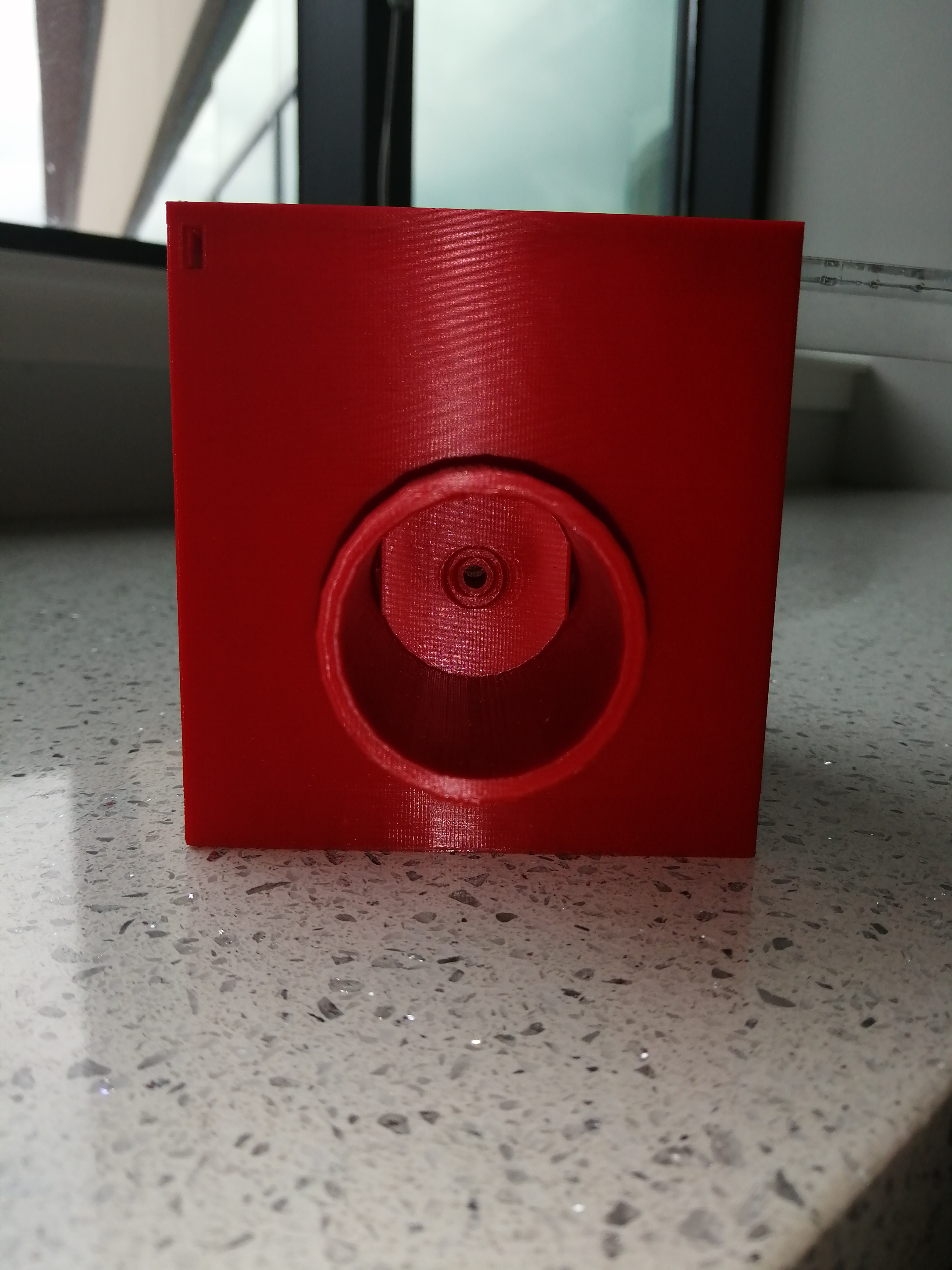
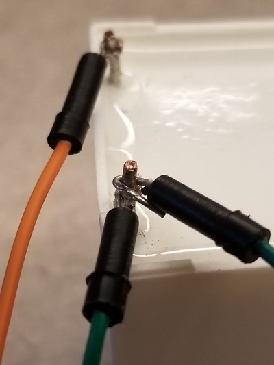
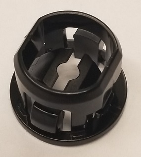
The cuvette chamber provides the delivery vehicle for the electric field that causes electroporation. The cuvette chamber was designed to keep inward pressure on the plug ends that contact the cuvette. Hands-free electroporation was an important consideration in our design. The built-in spring-like nature of the resulting connection ensures constant contact when like charges build up on each plug and its corresponding cuvette contact. It is also notable that we chose stackable banana plugs so that we could tandem a 1,000V multimeter to the cuvette holder; especially useful during pre-electroporation functions check.
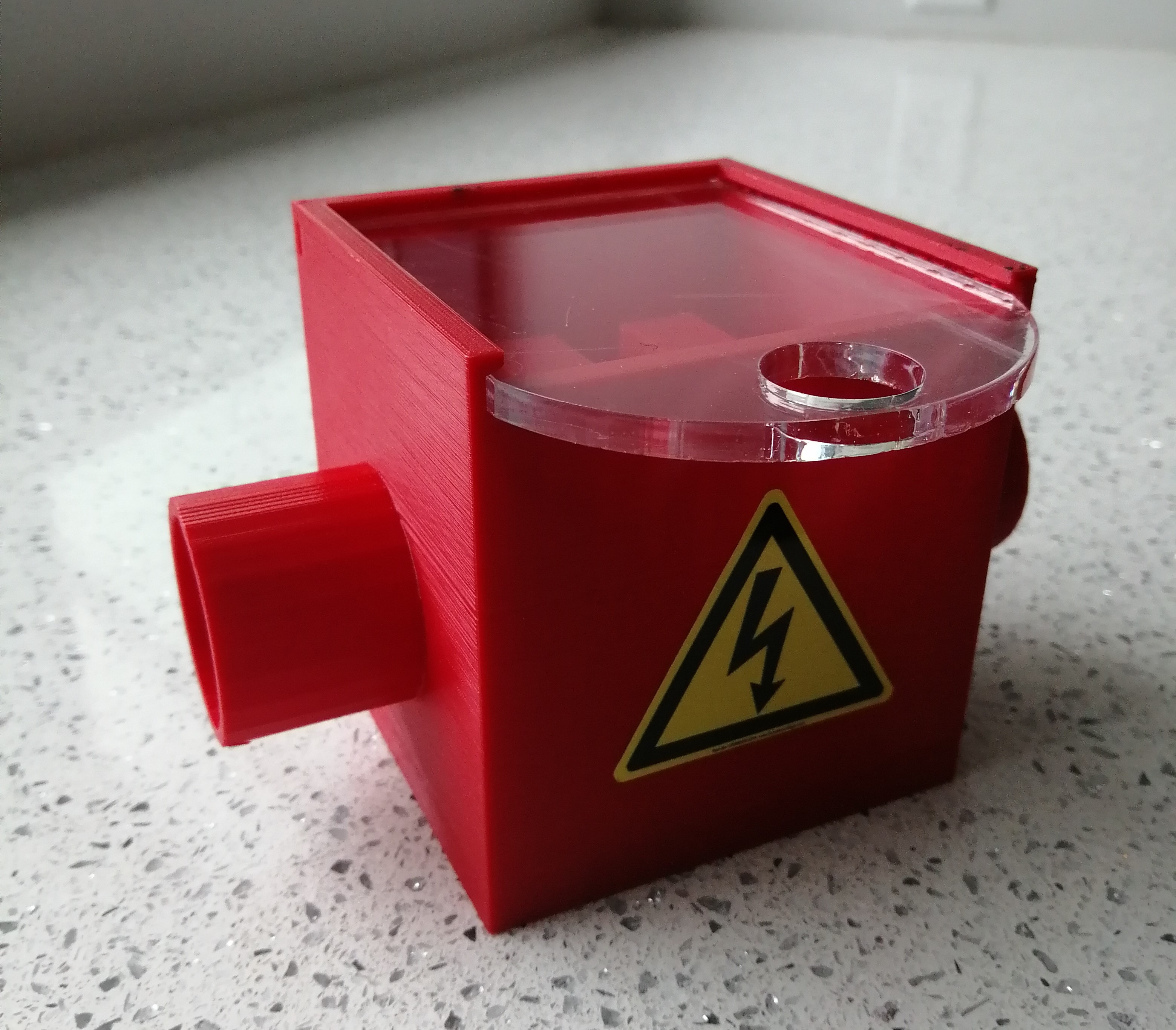
The cuvette chamber has several safety features. It is enclosed in a four-sided box with a removable lid that can be laser cut from a clear Poly acrylic sheet or 3D printed. Collars around lead connectors provide protection from shock exposure. Design and print files are included below. The chamber can be printed with various levels of fill; 15% fill is shown here and functioned well in our hands.
Print File: Cuvette Chamber.stl
CAD Design File: Cuvette Chamber CAD.dwg
IGES File: Cuvette Chamber.iges
Chamber Lid Laser Cut File: Chamber Lid.SVG
Chamber Lid Print File: Chamber Lid STL.stl
Chamber Lid CAD Design File: Chamber Lid CAD.dwg
Chamber Lid IGES File: Chamber Lid.iges
Note: IGES drawing files save vector image data to transfer information between different CAD applications. Graphics acceleration may have to be disabled in order for some open source CAD software to load.
Bill of Materials
|
Part |
Quantity |
Supplier |
Supplier part number |
URL |
|
Power supply banana plug test leads |
2 |
Mouser |
4911A-60/4911A-62 |
|
|
Test Lead Wire 25 in. red |
1 |
Powerwerx |
Wire-TL-18-00-25 |
|
|
Test Lead Wire 25 in. black |
1 |
Powerwerx |
Wire-TL-18-00-25 |
|
|
PCB Prototype padboard - 8cm x 12cm |
1 |
Amazon |
739340318574 |
|
|
Resistors - 8W-100kΩ |
6 |
Mouser |
279-ROX8J100K |
|
|
Resistors - 2W-1MΩ |
6 |
Mouser |
594-5083NW1M000J |
|
|
Bio-Rad Model 3000xi Computer Controlled Electrophoresis Power Supply (or similar capable of generating at least 1KV DC) |
1 |
ebay or other supplier of used scientific equipment |
|
|
|
3-Pin 5.08mm Pitch Male Female Plug-in PCB Screw Terminal Block Connector |
2 |
Amazon |
0766832280286 |
|
|
3-Position Screw Terminal Block |
2 |
Addicore |
AD305 |
|
|
Male-Male fixed length jumper wires |
5 |
Jameco |
2127718 |
|
|
Capacitor - 25μF - 1,300V |
1 |
Mouser |
C4AQUBW5250A3NJ |
|
|
Ring Terminals |
4 |
Lowes |
136093 |
|
|
DPDT toggle switch - 20A |
1 |
Ace Hardware |
GSW-16 |
|
|
3/8-in Plastic NM Connector |
2 |
Lowes |
44740 |
|
|
Junction box |
1 |
Lowes |
10029 |
|
|
3D printed cuvette holder |
1 |
|||
|
1kV Multimeter |
1 |
CEN-TECH (or similar) |
61593/P37772 |
|
|
Banana Jack Connector Standard Banana Solder Red/Black |
2 |
Digi-Key |
3185-FCR7350R-ND (or similar) |
|
|
ISO-3864 Warning Symbol Labels - High Voltage |
1x5 |
emedco |
SYM28R71VAD |
Modular Pulse Generator
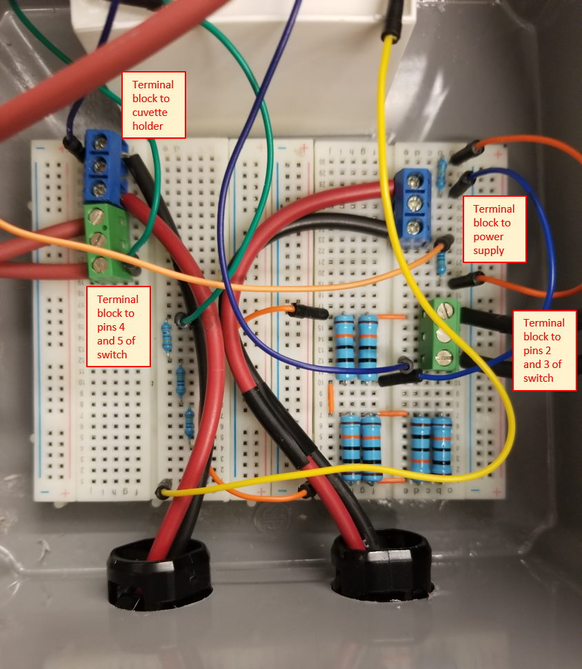
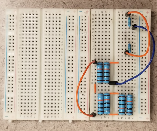
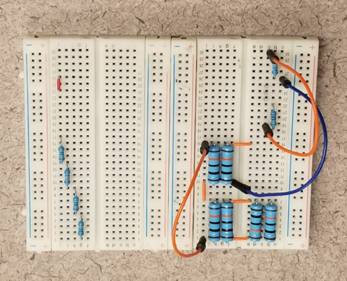
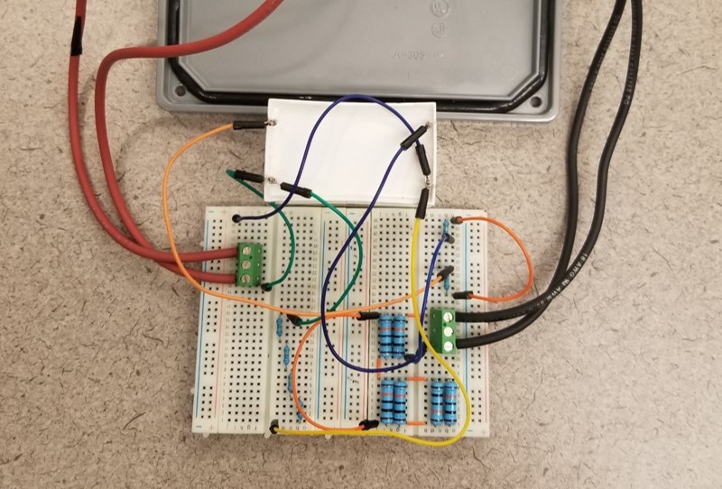
Components and configurations of the electrical circuit are described here. For all connections, refer to the circuit diagram and photos of the assembled circuit.
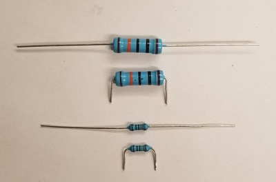
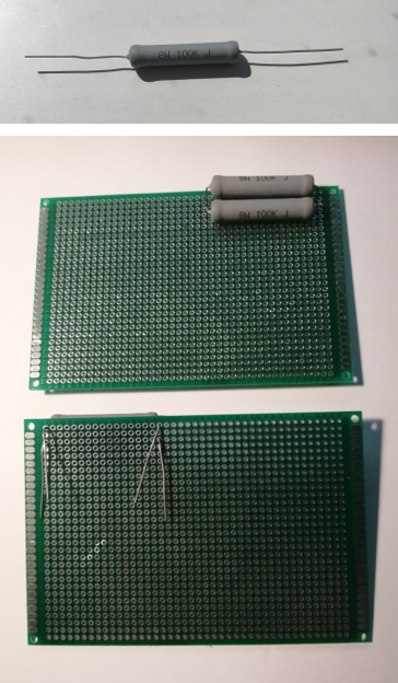
Clip resistor pins and bend at 90-degree angle to fit into breadboard terminals.
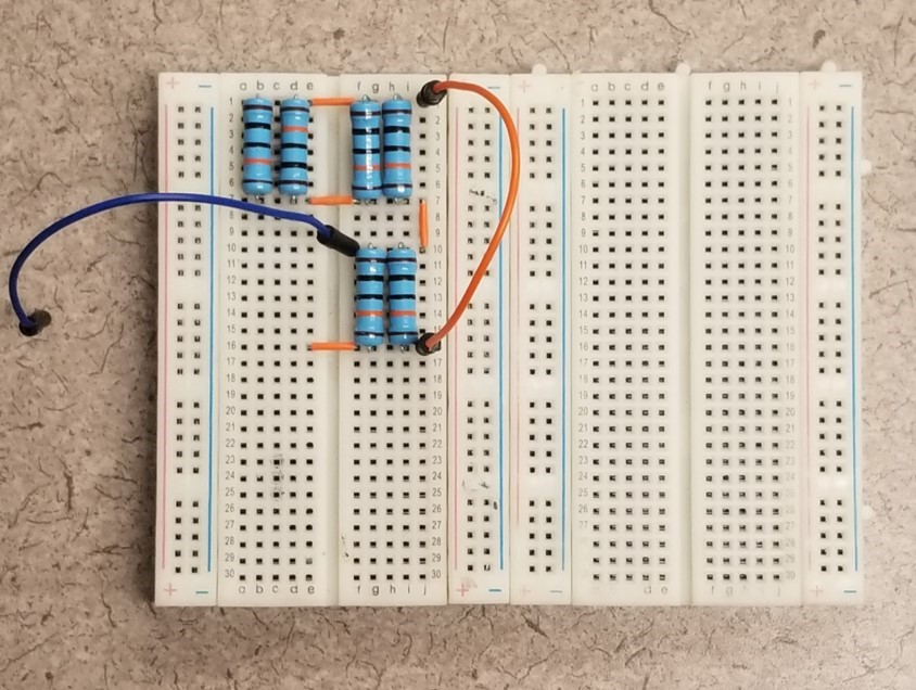
Connect six 100KΩ - 2W resistors (R3-R8) in parallel into breadboards using jumper wires as needed to form connections.
Connect two 1MΩ - 1/2W resistors (R1 and R2) in series into breadboards using jumper wires as needed to form connections.
Connect four 1MΩ - 1/2W resistors (R9-R12) in series. A short jumper wire is also placed on the board as shown (upper left section of breadboard) that will become a link between the terminal blocks connecting switch position four and the cuvette chamber.
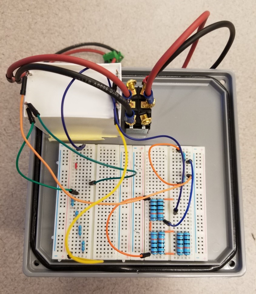
Ensure the 25μF - 1,300V capacitor is not charged before handling by measuring voltage across the terminals using the multimeter. Connect three 20cm flexible jumper wires to each pole of the capacitor. Note that two leads from each capacitor pole are present. Wire terminals can be crimped around capacitor leads or soldered for establishing a more permanent connection. Attach capacitor leads to the breadboard per circuit diagram and accompanying photos.
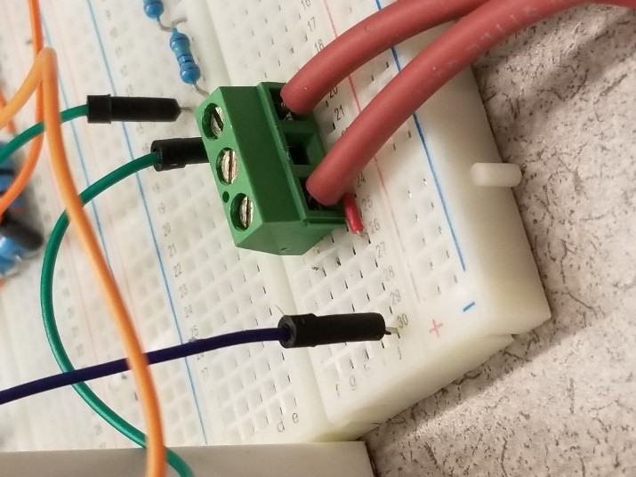
Connect terminal blocks from switch leads to the breadboard.
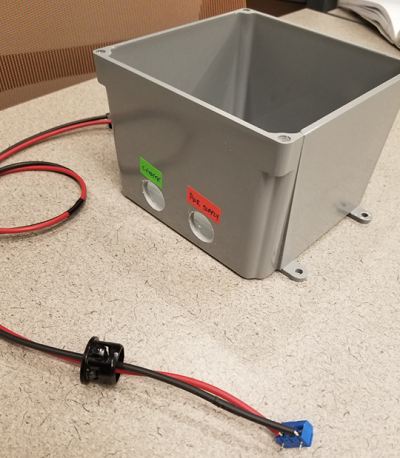
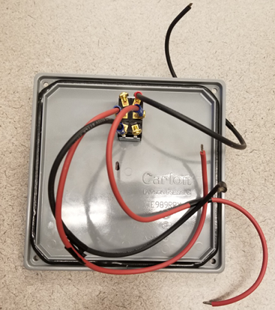
Cut one red and one black 60 in. test lead in half. Strip ends to leave approximately 5mm of bare wire. It might be helpful to tape the two pairs of one red and one black wire together every few centimeters. Pass stripped wire ends through NM plastic connectors about 10cm. Connect terminal blocks to the stripped ends by inserting paired wires into outside wire cages of terminal blocks, then tighten terminal block screws. Push NM plastic connectors into the cable pass-through holes of the enclosure (note that only two 22mm holes need to be made in the modular pulse generator enclosure, compared to three in the standard pulse generator enclosure).
Pull the terminal block ends of the power supply and cuvette holder cables further through the pass-through holes with only sufficient play to insert the terminal blocks into the appropriate places on the breadboards.
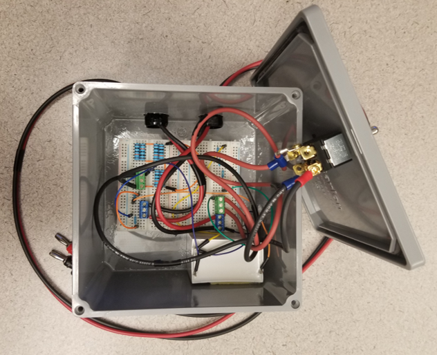
Adhere the breadboards and capacitor to the inside base of the enclosure. While we used 2-sided tape, glue could be used for a more permanent solution. Connect power supply and cuvette holder terminal blocks to the breadboard.
Attach enclosure cover.
Bill of Materials
|
Part |
Quantity |
Supplier |
Supplier part number |
URL |
|
400 Point solderless breadboard |
2 |
Jameco |
20601 |
|
|
Male-Male fixed length jumper wires |
1 |
Jameco |
2127718 |
|
|
Test Lead Wire 25 in. red |
1 |
Powerwerx |
Wire-TL-18-00-25 |
|
|
Test Lead Wire 25 in. black |
1 |
Powerwerx |
Wire-TL-18-00-25 |
|
|
Male-Male flexible jumper wires |
1 |
Walmart |
NA |
|
|
Capacitor - 25μF - 1,300V |
1 |
Mouser |
C4AQUBW5250A3NJ |
|
|
Red banana plug test lead - 60 inch |
1 |
Mouser |
B-60-2 |
|
|
Black banana plug test lead - 60 inch |
1 |
Mouser |
B-60-0 |
|
|
Ring Terminals |
4 |
Lowes |
136093 |
|
|
Resistor - 1MΩ - 500mW |
6 |
Mouser |
71-CMF551M0000BHEK |
|
|
Resistor - 100kΩ - 2W |
6 |
Mouser |
603-MFR200FRF52-100K |
|
|
3-Position Screw Terminal Block |
4 |
Addicore |
AD305 |
|
|
DPDT toggle switch - 20A |
1 |
Ace Hardware |
GSW-16 |
|
|
3/8-in Plastic NM Connector |
2 |
Lowes |
44740 |
|
|
Junction box |
1 |
Lowes |
10029 |
|
|
3D printed cuvette holder |
1 |
|||
|
Multimeter |
1 |
CEN-TECH |
61593/P37772 |
|
|
1KV DC Power supply (e.g., Bio-Rad PowerPac 1000) |
1 |
Bio-Rad (or other) |
||
|
Red banana plug test lead - 24 inch - 15A |
1 |
Mouser |
B-24-2 |
|
|
Black banana plug test lead - 24 inch |
1 |
Mouser |
B-24-0 |
|
|
Horizontal Gel Electrophoresis System |
1 |
Thermo Fisher Scientific |
FB-SB-710 (or similar) |
Authors
|
Name |
|
Affiliation |
|
|
Michael Cauchy |
mcauchy@oswego.edu |
State University of New York at Oswego |
|
|
Ali A. Khan |
akhan3@oswego.edu |
State University of New York at Oswego |
|
|
Yulia Artemenko |
yulia.artemenko@oswego.edu |
State University of New York at Oswego |
|
|
David A. Dunn |
david.dunn@oswego.edu |
State University of New York at Oswego |